 Smart Blind Stick Project using Arduino and Sensors
Ever heard of Hugh Herr? He is a famous American rock climber who has shattered the limitations of his disabilities; he is a strong believer that technology could help disabled persons to live a normal life. In one of his TED talk Herr said “Humans are not disabled. A person can never be broken. Our built environment, our technologies, is broken and disabled. We the people need not accept our limitations, but can transfer disability through technological Innovation”. These were not just words but he lived his life to them, today he uses Prosthetic legs and claims to live to normal life. So yes, technology can indeed neutralize human disability; with this in mind let us use the power of Arduino and simple sensors to build a Blind man’s stick that could perform more than just a stick for visually impaired persons.
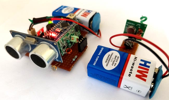
This Smart stick will have an Ultrasonic sensor to sense distance from any obstacle, LDR to sense lighting conditions and a RF remote using which the blind man could remotely locate his stick. All the feedbacks will be given to the blind man through a Buzzer. Of course you can use a vibrator motor in place of Buzzer and advance a lot more using your creativity.
Materials Required:
- Arduino Nano (Any version will work)
- Ultrasonic Sensor HC-SR04
- LDR
- Buzzer and LED
- 7805
- 433MHz RF transmitter and receiver
- Resistors
- Push button
- Perf board
- Soldering Kit
- 9V batteries
Circuit Diagram:
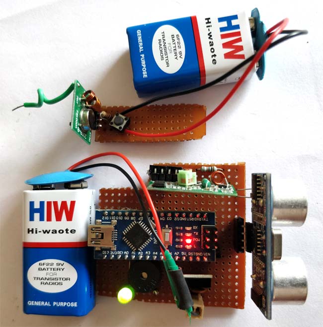
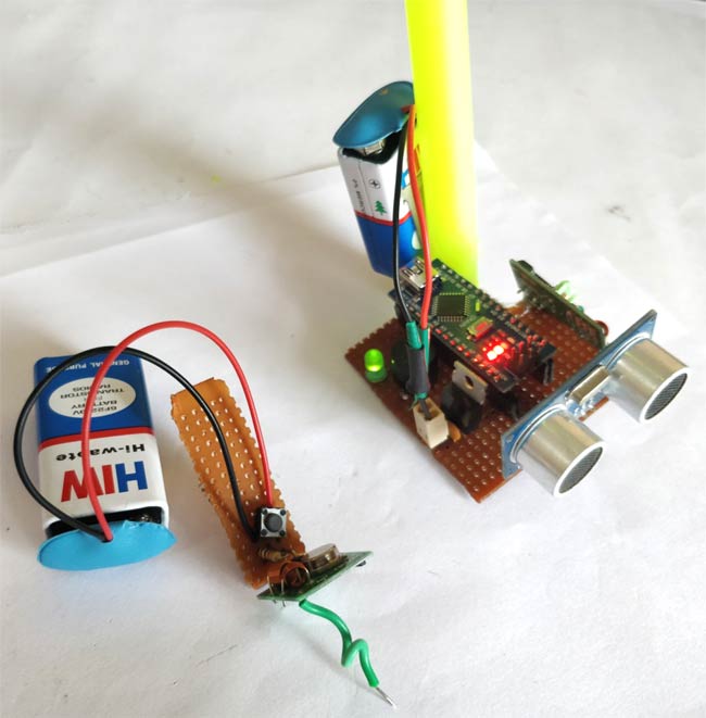
This Arduino Smart Blind Stick Project requires two separate circuits. One is the main circuit which will be mounted on the blind man’s stick. The other is a small remote RF transmitter circuit which will be used to locate the main circuit. The main board’s circuit diagram is shown below:

As we can see an Arduino Nano is used to control all the sensors. The complete board is powered by a 9V battery which is regulated to +5V using a 7805 Voltage regulator. The Ultrasonic sensor is powered by 5V and the trigger and Echo pin is connected to Arduino nano pin 3 and 2 as shown above. The LDR is connected with a resistor of value 10K to form a Potential divider and the difference in voltage is read by Arduino ADC pin A1. The ADC pin A0 is used to read the signal from RF receiver. The output of the board is given by the Buzzer which is connected to pin 12.
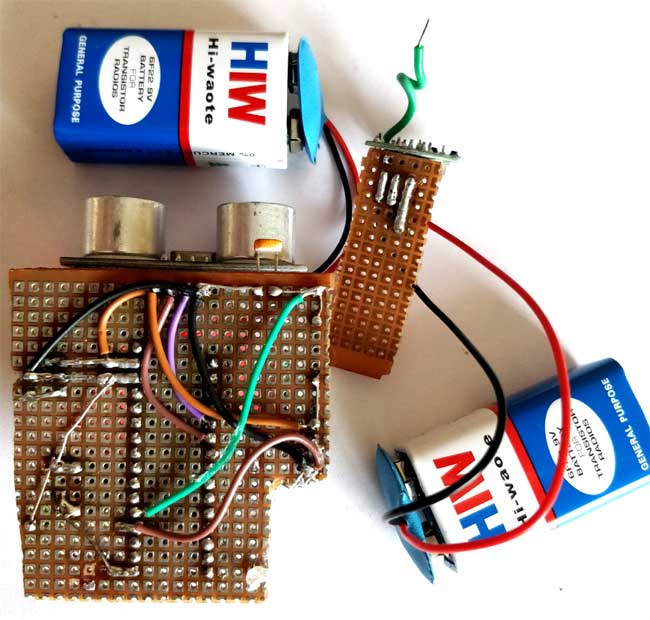
I have used a small hack to make this RF remote control circuit to work. Normally while using this 433 MHz module requires an Encoder and Decoder or two MCU to work. But, in our application we just need the receiver to detect if the transmitter is sending some signals. So the Data pin of the transmitter is connected to Ground or Vcc of the supply.
The data pin of the receiver is passed through an RC filter and then given to the Arduino as shown below. Now, whenever the button is pressed the Receiver output some constant ADC value repeatedly. This repetition cannot be observed when the button is not pressed. So we write the Arduino program to check for repeated values to detect if the button is pressed. So that is how a Blind person can track his stick. You can check here: how RF transmitter and receiver work.
I have used a perf board to solder all the connections so that it gets intact with the stick. But, you can also make them on a breadboard. The boards that I made are below.
Arduino Program for Smart Blind Stick:
Once we are ready with our hardware, we can connect the Arduino to our Computer and start programming. The complete code used for this page can be found at the bottom of this page, you can upload it directly to your Arduino board. However, if you are curious to know how the code works read further.
Like all programs we start with void setup() to initialise Input Output pins. In our program the Buzzer and Trigger pin is an Output device and the Echo pin is an Input device. We also initialise the serial monitor for debugging.
void setup()
{
Serial.begin(9600);
pinMode(Buzz,OUTPUT);
digitalWrite(Buzz,LOW);
pinMode(trigger, OUTPUT);
pinMode(echo, INPUT);
}
Inside the main loop we are reading all the sensors data. We begin with reading the sensor data of Ultrasonic sensor for distance, LDR for light intensity and RF signal to check if the button is pressed. All these data is saved in a variable as shown below for future use.
calculate_distance(trigger,echo);
Signal = analogRead(Remote);
Intens = analogRead(Light);
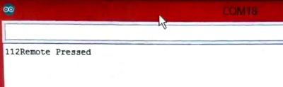
We start with checking for the Remote signal. We use a variable called similar_count to check how many times the same values are being repeated from the RF receiver. This repetition will occur only when the button is pressed. So we trigger the Remote pressed alarm if the count exceeds a value of 100.
//Check if Remote is pressed
int temp = analogRead(Remote);
similar_count=0;
while (Signal==temp)
{
 Signal = analogRead(Remote);
 similar_count++;
}

//If remote pressed
if (similar_count<100)
{
  Serial.print(similar_count); Serial.println("Remote Pressed");
  digitalWrite(Buzz,HIGH);delay(3000);digitalWrite(Buzz,LOW);
}
You can also check it on Serial Monitor on your computer:
Next we check for the intensity of light around the blind man. If the LDR gives a value of less than 200 it is assumed to be very dark and we give him the warning through buzzer with a specific tone of delay with 200ms. If the intensity is very bright that is more than 800 then also we give a warning with another tone. The alarm tone and intensity can be easily varied by changing the respective value in the below code.
//If very dark
if (Intens<200)
{
  Serial.print(Intens); Serial.println("Bright Light");
  digitalWrite(Buzz,HIGH);delay(200);digitalWrite(Buzz,LOW);delay(200);digitalWrite(Buzz,HIGH);delay(200);digitalWrite(Buzz,LOW);delay(200);
  delay(500);
}

//If very bright
if (Intens>800)
{
  Serial.print(Intens); Serial.println("Low Light");
  digitalWrite(Buzz,HIGH);delay(500);digitalWrite(Buzz,LOW);delay(500);digitalWrite(Buzz,HIGH);delay(500);digitalWrite(Buzz,LOW);delay(500);
}
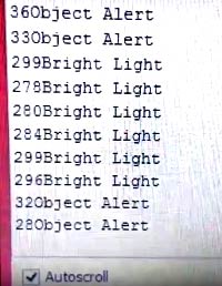
Finally, we start measuring the distance from any obstacle. There will be no alarm if the measured distance is more than 50cm. But, if it is less than 50cm the alarm will start by beeping the buzzer. As the object gets closer to the buzzer the beeping interval will also decrease. The closer the object is the faster the buzzer will beep. This can be done by creating a delay that is proportional to the distance measured. Since the delay () in Arduino cannot accept variables we have to use a for loop which loop based on the measured distance as shown below.
if (dist<50)
{
  Serial.print(dist); Serial.println("Object Alert");
  digitalWrite(Buzz,HIGH);
  for (int i=dist; i>0; i--)
    delay(10);
  digitalWrite(Buzz,LOW);
  for (int i=dist; i>0; i--)
    delay(10);
}
Learn more about measuring the distance using Ultrasonic sensor and Arduino.
The program can be easily adapted for your application by changing the value which we use to compare. You use the serial monitor to debug if a false alarm is trigger. If you have any problem you can use the comment section below to post your questions
Arduino Blind Stick in Action:
Finally it’s time to test our project. Make sure the connections are done as per the circuit diagram and the program is successfully uploaded. Now, power both the circuits using a 9V battery and you should start to see results. Move the Ultra Sonic sensor closer to object and you will notice the Buzzer beeping and this beeping frequency increases as the stick goes closer to object. If the LDR is covered in dark or if there is too much light the buzzer will beep. If everything is normal the buzzer will not beep.
When you press the button on the remote the buzzer will give a long beep. The complete working of this Smart Blind Stick is shown in the Video given at the end of this page. I also use a small stick to mount the complete assembly you can use a larger one or an actual blind stick and put it in action.
If your buzzer is always beeping it means the alarm is being false triggered. You can open the serial monitor to check for the parameters and check which is falling in critical and adjust that. As always you can post your problem in the comment section to get help. Hope you understood the project and enjoyed building something.
Code:
/*
* Program for Blind Man Stick
* Code by B.Aswinth Raj
* Dated: 03-11-2017
* Website: www.circuitdigest.com
*/
* Program for Blind Man Stick
* Code by B.Aswinth Raj
* Dated: 03-11-2017
* Website: www.circuitdigest.com
*/
const int trigger = 3; //Trigger pin of 1st Sesnor
const int echo = 2; //Echo pin of 1st Sesnor
const int Buzz = 13; //Echo pin of 1st Sesnor
const int Remote = A0; //Echo pin of 1st Sesnor
const int Light = A1; //Echo pin of 1st Sesnor
const int echo = 2; //Echo pin of 1st Sesnor
const int Buzz = 13; //Echo pin of 1st Sesnor
const int Remote = A0; //Echo pin of 1st Sesnor
const int Light = A1; //Echo pin of 1st Sesnor
long time_taken;
int dist;
int Signal;
int Intens;
int similar_count;
int dist;
int Signal;
int Intens;
int similar_count;
void setup() {
Serial.begin(9600);
pinMode(Buzz,OUTPUT);
digitalWrite(Buzz,LOW);
pinMode(trigger, OUTPUT);
pinMode(echo, INPUT);
Serial.begin(9600);
pinMode(Buzz,OUTPUT);
digitalWrite(Buzz,LOW);
pinMode(trigger, OUTPUT);
pinMode(echo, INPUT);
}
/*###Function to calculate distance###*/
void calculate_distance(int trigger, int echo)
{
digitalWrite(trigger, LOW);
delayMicroseconds(2);
digitalWrite(trigger, HIGH);
delayMicroseconds(10);
digitalWrite(trigger, LOW);
void calculate_distance(int trigger, int echo)
{
digitalWrite(trigger, LOW);
delayMicroseconds(2);
digitalWrite(trigger, HIGH);
delayMicroseconds(10);
digitalWrite(trigger, LOW);
time_taken = pulseIn(echo, HIGH);
dist= time_taken*0.034/2;
if (dist>300)
dist=300;
}
dist= time_taken*0.034/2;
if (dist>300)
dist=300;
}
void loop() { //infinite loopy
calculate_distance(trigger,echo);
Signal = analogRead(Remote);
Intens = analogRead(Light);
calculate_distance(trigger,echo);
Signal = analogRead(Remote);
Intens = analogRead(Light);
//Check if Remote is pressed
int temp = analogRead(Remote);
similar_count=0;
while (Signal==temp)
{
Signal = analogRead(Remote);
similar_count++;
}
int temp = analogRead(Remote);
similar_count=0;
while (Signal==temp)
{
Signal = analogRead(Remote);
similar_count++;
}
//If remote pressed
if (similar_count<100)
{
Serial.print(similar_count); Serial.println("Remote Pressed");
digitalWrite(Buzz,HIGH);delay(3000);digitalWrite(Buzz,LOW);
}
if (similar_count<100)
{
Serial.print(similar_count); Serial.println("Remote Pressed");
digitalWrite(Buzz,HIGH);delay(3000);digitalWrite(Buzz,LOW);
}
//If very dark
if (Intens<200)
{
Serial.print(Intens); Serial.println("Bright Light");
digitalWrite(Buzz,HIGH);delay(200);digitalWrite(Buzz,LOW);delay(200);digitalWrite(Buzz,HIGH);delay(200);
if (Intens<200)
{
Serial.print(Intens); Serial.println("Bright Light");
digitalWrite(Buzz,HIGH);delay(200);digitalWrite(Buzz,LOW);delay(200);digitalWrite(Buzz,HIGH);delay(200);
digitalWrite(Buzz,LOW);delay(200);
delay(500);
}
delay(500);
}
//If very bright
if (Intens>800)
{
Serial.print(Intens); Serial.println("Low Light");
digitalWrite(Buzz,HIGH);delay(500);digitalWrite(Buzz,LOW);delay(500);digitalWrite(Buzz,HIGH);delay(500);
if (Intens>800)
{
Serial.print(Intens); Serial.println("Low Light");
digitalWrite(Buzz,HIGH);delay(500);digitalWrite(Buzz,LOW);delay(500);digitalWrite(Buzz,HIGH);delay(500);
digitalWrite(Buzz,LOW);delay(500);
}
}
if (dist<50)
{
Serial.print(dist); Serial.println("Object Alert");
digitalWrite(Buzz,HIGH);
for (int i=dist; i>0; i--)
delay(10);
{
Serial.print(dist); Serial.println("Object Alert");
digitalWrite(Buzz,HIGH);
for (int i=dist; i>0; i--)
delay(10);
digitalWrite(Buzz,LOW);
for (int i=dist; i>0; i--)
delay(10);
}
for (int i=dist; i>0; i--)
delay(10);
}
//Serial.print("dist=");
//Serial.println(dist);
//Serial.print("Similar_count=");
//Serial.println(similar_count);
//Serial.print("Intens=");
//Serial.println(Intens);
}
//Serial.println(dist);
//Serial.print("Similar_count=");
//Serial.println(similar_count);
//Serial.print("Intens=");
//Serial.println(Intens);
}
Video:
Comments
Post a Comment